Diode-Compression Power Amplifier
This circuit is an attempt at using diode-compression within a power amplifier. It's based on a design by Bruce Depalma as published here.
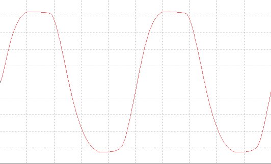
The diodes provide peak compression when the amplifier is driven hard. (For hi-fi use, the diodes may be replaced with jumpers and the 470K resistor eliminated. The waveforms below show the difference.)
DePalma basically designed a solid-state version of the Williamson Amplifier, which takes feedback to the input cathode. This arrangement is extremely stable, and the audio quality is excellent.
Circuit Notes:
Resistors are 1/4W unless noted.
Connect the three points marked "FB" together.
470K controls compression level. (Values between 100K - 470K are acceptable.)
The .1uF/1K network alters the gain and frequency response. (The default value is suitable for use with 9V preamp circuits.)
Transistors in the second stage need small heatsinks.
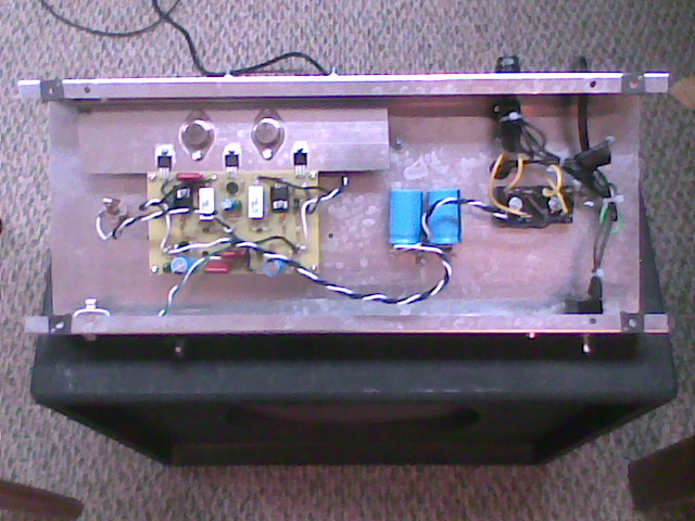
Vbe multiplier goes between the output transistors on the heatsink (see pictures below).
Volume control is a 10K audio taper before the input cap.
Biasing:
Before connecting speakers, trim the balance control to get zero volts at the output.
Connect a voltmeter between the output emitters, and adjust the bias to get 75mV. Note: You may have to go back and forth between the two controls, as one can throw the other off.
Connect the speaker (or load resistor) and double-check the values again.
Let it warm up for awhile, check again, then glue the trimpots into place with silicone adhesive.
Normal Operation:
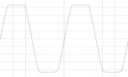
Diodes in Effect:
Pictures:
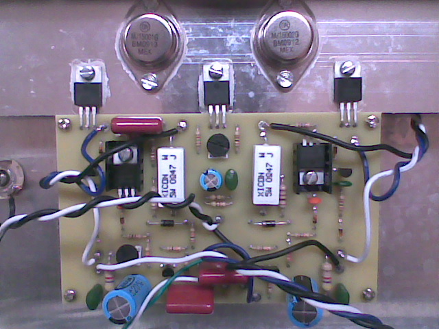
|