
Building Gus Smalley's NPN Boost
by Aron Nelson
10/3/03 version 2
First of all, get your parts ready. The board will be built first. As you can see, perfboard has copper plated holes on one side for you to solder your components.
Yep, I keep my components in coin envelopes. (Thanks R.G.!)
 Here's a picture of the
type of soldering iron tip I use. As you can see it's pointed like a pen. This
kind of tip is great for working with small parts and boards. OK, turn your
iron on, and wet your sponge for your iron. On my Weller soldering station,
I keep the iron heat slightly above 3. (I have no idea what temperature that
is)
Here's a picture of the
type of soldering iron tip I use. As you can see it's pointed like a pen. This
kind of tip is great for working with small parts and boards. OK, turn your
iron on, and wet your sponge for your iron. On my Weller soldering station,
I keep the iron heat slightly above 3. (I have no idea what temperature that
is)
 Here's part of the DIP8
socket that I am cutting to make a makeshift transistor socket. Since most of
the transistors I am going to use are "flat" in terms of the leads
(all in a row), this kind of socket works well for them.
Here's part of the DIP8
socket that I am cutting to make a makeshift transistor socket. Since most of
the transistors I am going to use are "flat" in terms of the leads
(all in a row), this kind of socket works well for them.
 On the top is the makeshift
socket. Below is the standard transistor socket that you can usually order.
On the top is the makeshift
socket. Below is the standard transistor socket that you can usually order.
The next step is to cut the perfboard. This circuit not really large so I don't need to work with the whole board.
 I use my transistor socket
as a guide to figure out how tall the board should be. I will be standing the
resistors "on end" to save space so I know I only need about 3 holes
above the socket since the resistor takes up two by itself.
I use my transistor socket
as a guide to figure out how tall the board should be. I will be standing the
resistors "on end" to save space so I know I only need about 3 holes
above the socket since the resistor takes up two by itself.
Notice that I have another piece of perfboard as a scoring device. You should probably use a metal ruler.
 OK, now I know the size
and will use my trusty Xacto knife to score and snap the board.
OK, now I know the size
and will use my trusty Xacto knife to score and snap the board.
 Here is the board with
the score marks from the Xacto knife. Just snap the board with your fingers
and it will break right on the score mark. Trim the edges off after the fact
with your pliers and cutter.
Here is the board with
the score marks from the Xacto knife. Just snap the board with your fingers
and it will break right on the score mark. Trim the edges off after the fact
with your pliers and cutter.
 Now I'm going to place
the first component on the board. I always work left to right on my boards.
So I will start with the input capacitor (.1uF cap).
Now I'm going to place
the first component on the board. I always work left to right on my boards.
So I will start with the input capacitor (.1uF cap).
 Since the capacitor is
"wide", what I like to do is bend the leads so that the capacitor
takes up less space under the board (the copper side). Use your needle nose
pliers to do this. No need to do this if your capacitor is small. Film capacitors
tend to be on the large side. Anyway, I like those green caps for a smoother,
mellower tone.
Since the capacitor is
"wide", what I like to do is bend the leads so that the capacitor
takes up less space under the board (the copper side). Use your needle nose
pliers to do this. No need to do this if your capacitor is small. Film capacitors
tend to be on the large side. Anyway, I like those green caps for a smoother,
mellower tone.
 Here's how it goes into
the board.
Here's how it goes into
the board.
 Here's what it looks like
from the bottom of the board.
Here's what it looks like
from the bottom of the board.
 Your iron should be hot
enough now, remember to clean the tip, put the tip on the copper touching the
copper pad and lead and apply solder. Don't put too much solder.
Your iron should be hot
enough now, remember to clean the tip, put the tip on the copper touching the
copper pad and lead and apply solder. Don't put too much solder.
Since I know components will be connecting the capacitor lead after the input cap, I allow for a space between the capacitor and the socket. As you can see, I left 3 holes between the input cap and socket.
The middle lead of the socket is the base of the transistor so I place the socket so that the input cap touches the middle lead. If at all possible I clip the lead so it's roughly in the center of the copper pad.
 As I take a look at the
schematic, I notice that the trickiest part of the schematic is really the part
"under" the transistor and input cap. I could work from the "front"
of the circuit, but in this case, I decide to put in the 22uF capacitor that's
under the transistor. See that stripe on the bottom, that's negative. That side
should be facing the right side of the board away from the input cap.
As I take a look at the
schematic, I notice that the trickiest part of the schematic is really the part
"under" the transistor and input cap. I could work from the "front"
of the circuit, but in this case, I decide to put in the 22uF capacitor that's
under the transistor. See that stripe on the bottom, that's negative. That side
should be facing the right side of the board away from the input cap.
A large part of doing perfboard is modifying your layout on the fly when you realize that something might lie a bit easier on the board.
I keep chanting the golden rule:
If I connect the components together correctly, it will work. It doesn't matter if they are "in the air" or on cardboard, as long as they are connected together correctly (not shorting), the circuit will work.
 As I place the capacitor
under the transistor, I make a decision that placing the capacitor one hole
to the right will give me more room on my perfboard layout. Remember
the golden rule above.
As I place the capacitor
under the transistor, I make a decision that placing the capacitor one hole
to the right will give me more room on my perfboard layout. Remember
the golden rule above.
 Next up, the 10K resistor.
Notice how I bend the leads so that the resistor will stick up from the board.
Next up, the 10K resistor.
Notice how I bend the leads so that the resistor will stick up from the board.
 OK, my 10K is placed on
the board, next up is the 47K resistor.
OK, my 10K is placed on
the board, next up is the 47K resistor.
 OK, here's the back of
the board with the 10K and 47K resistor placed. I just bend the leads over the
other leads, then solder them.
OK, here's the back of
the board with the 10K and 47K resistor placed. I just bend the leads over the
other leads, then solder them.
 OK, the resistors are
soldered.
OK, the resistors are
soldered.
 Here's how our board looks
so far.
Here's how our board looks
so far.
 I'm going to do the output
cap next and 10K resistor next. OOOPS, I only have 10uF, 100V low ESR caps,
oh well, that's OK. It will work, but take up more space. Remember that stripe
is the negative side and should face the right side of the board away from the
input cap.
I'm going to do the output
cap next and 10K resistor next. OOOPS, I only have 10uF, 100V low ESR caps,
oh well, that's OK. It will work, but take up more space. Remember that stripe
is the negative side and should face the right side of the board away from the
input cap.
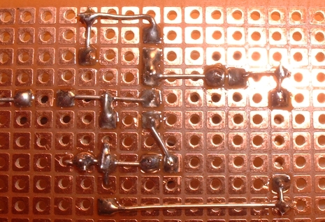
Here is the back of the board with the 10K bias resistor (vertical) connected to the transistor socket (collector pin) and the 10uF output cap (horizontal).
 Here's the back of the
board with output capacitor and 10K resistor placed.
Here's the back of the
board with output capacitor and 10K resistor placed.
 OK, solder the output
capacitor and 10K resistor in place.
OK, solder the output
capacitor and 10K resistor in place.
Here's pictures of the top of the board:


 OK, now to the 100K resistor
on the output. Well, we can lay that one down since it needs to take up so much
space on the board.
OK, now to the 100K resistor
on the output. Well, we can lay that one down since it needs to take up so much
space on the board.
 Very interesting. I only
had 1/2 watt resistors in 100K (for my amps), so I use it anyway. Yes, it will
work.
Very interesting. I only
had 1/2 watt resistors in 100K (for my amps), so I use it anyway. Yes, it will
work.
Now for the tricky 100K resistor close to the input cap. Hmmm, I would like to "jump it" over the input cap lead - that was my plan. I was going to keep the resistor on the bottom of the board and jump the lead over the input cap lead, but then I realize, I can simply lay the resistor on its side since there's enough room.
 See how it can fit?
 Here's how the resistor
lead is placed from the back of the board.
Here's how the resistor
lead is placed from the back of the board.
OK, now connect the 10K bias resistor to the 100K resistor that you just put in. Simply bend the 10K remaining lead and make it join the 100K resistor, then solder in place.
 Here it is, soldered in
place.
Here it is, soldered in
place.
Our finished board:
 Back
Back
and front:


Just wires next......