To get signal in and out, we need to add the two jacks and some coupling capacitors, C1 and C4. To control the volume, we need the 100K pot at the output, and to control the gain, we need the 50K pot connected through capacitor C2 to the feedback loop. We do not need the clipper diodes to get sound, so we will skip over those for the moment.
Disconnect your battery and install the needed resistors and jumpers first:
We do not need R1 for our breadboard layout. That is a pull-down resistor to prevent popping by capacitor C1 when switching the effect on and off. So let's leave it out.
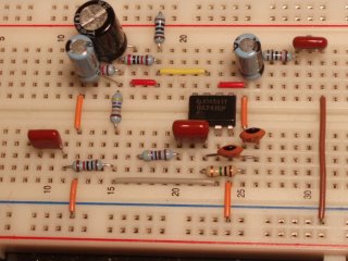
Now put in the capacitors
This gives a board that loooks like this:
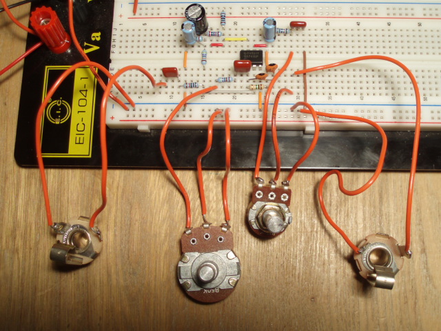
Finally, solder solid core wire to the lugs of the jacks and pots and
and you will have something like this:
There is one tricky thing about the ground rail connections. As I mentioned earlier, the power rails don't always run the entire length of the board. For flexibility, there is a break half way. If you have such a break and make your ground connections on the wrong side of the break, then you will not be making the necessary connections to ground. So, as a final precaution, use the continuity check on your multimeter to confirm that all of the grounded items are actually grounded.
Now you are ready for the big moment. Try it out!
The first time I tried it, I got a big buzzy noise. But I had connected the ground for the output jack into the the power rail below the ground rail on my breadboard. When I got it properly connected to the ground rail, everything was fine. You will find lots of volume and "overdrive."
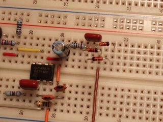
To complete your build of the Overdrive 250, disconnect your battery and add the diode clippers:
Now you can listen for the difference a diode makes. Congrats! You are done. Or not. You may want to experiment with some of the component values. For example, the MXR Distortion Plus has a very similar layout but some very different values. You might try those. Or you can combine this project with the Diode Compression Op Amp project by replacing the LM741 with a discrete version. This shows the beauty of the breadboard: it's easy to try something else.