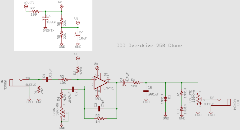
Now let's start to build up the circuit from the beginning. We are going to begin with the power section. On the schematic, that refers to this block:
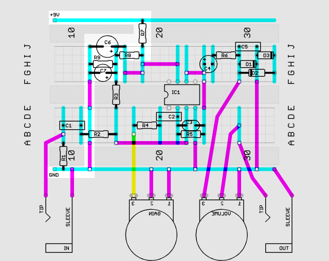
This corresponds to this part of the layout:
To prepare the power rails, we are going to connect solid core wires between the rails and the terminal posts on the bread board. The leads of the battery clip are connected to these posts as well. I recommend that you do not hook the battery leads directly to the bread board by sticking them into the holes. The battery leads are stranded wire and the strands can break off in the holes and ruin them.
For the moment, leave the battery clip disconnected from your 9V battery.
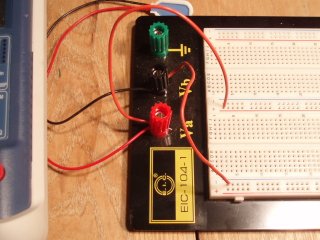
The black battery lead is going to the black terminal post and the red battery lead is going to the red terminal post. The black terminal post is connected by solid core wire to the negative blue rail on the bottom. The red terminal post is connected to the positive red rail in the middle of the bread board. All of these labels are merely for convenience. It is not actually necessary to use a rail marked positive for a positive voltage.
Let's put the power section together in two stages, with just resistors first and then we'll add the capacitors.
We need only the resistors R7, R8, and R9 and two jumpers:
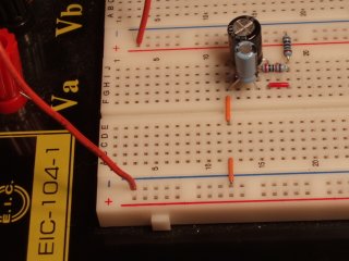
This is what the result looks like:
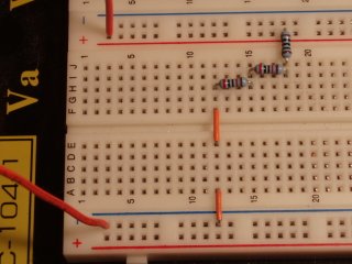
Omitting the capacitors from the power section, these three resistors just run in a series from the positive rail to the ground rail. You might want to look at the schematic to confirm this. Also, look at your breadboard after carrying out the steps above and check that this is what you have done: R7 goes from the positive rail to R8 which connects to R9 which connects to ground.
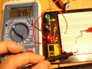
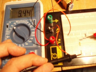
Now let's hook up the battery to the battery clip and check some voltages. The following pictures show what I get, touching the black probe to the ground rail and the red probe to the positive rail, the junction between R7 and R8, the junction between R8 and R9, and the grounded lead of R9.
 |
 |
|---|---|
 |
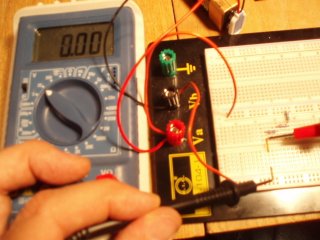 |
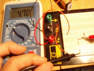
My battery was reading 9.46V. After the 100Ω resistor, the voltage drops to 9.44V. After the first 22KΩ resistor, the voltage drops to 4.70V, which is approximately half of the 9.44V. And, of course, after the second 22KΩ resistor, we read ground.
What you are seeing here is the effect of a voltage divider. The two 22KΩ resistors are dividing the 9.44V fed to them in half at their junction. This is half-way voltage is needed for the op amp to amplify the AC (alternating current) audio signal that goes into the circuit. The circuit is constrained by the 9V battery to voltages between approximately 0V and 9V. So inside the circuit, the AC audio signal is going to fluctuate around the mid point set by this voltage divider. We will return to this later.
The behaviour of the voltage divider is a direct consequence of Ohm's law:
V = I × R
where V is the voltage difference, I is the current (in amperes), and R is the resistance (in ohms). We can apply Ohm's law right away to infer how much current is going through our circuit. Across the 100Ω resistor R7, the voltage difference is approximately 0.02V (9.46V minus 9.44V). Therefore the current is approximately
I = V/R = 0.02/100 = 0.0002A = 0.2mA
You can use your multimeter to measure the current directly and compare it with a prediction based on your measurements.
In the voltage divider, the current through the two resistors in series is the same. If the resistances are equal, then Ohm's law says that the voltage drop across both resistors is the same. Given that the two voltage drops have to add up to the overall voltage drop, the voltage at the junction of the resistors has to be half of the overall voltage.
Notice that two 10KΩ or two 1MΩ resistors would do the same voltage division. The effect of changing the value of the pair of resistors is only on the current. The larger the resistors are the smaller the current will be. This is useful for understanding an important difference between this circuit, the DOD Overdrive 250, and a closely related one, the MXR Distortion Plus.
To complete the power section, disconnect the battery and put in capacitors C6 and C7:
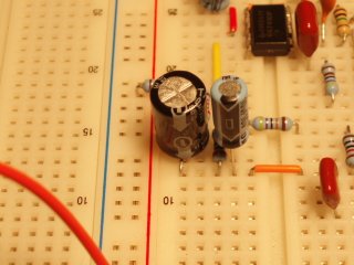
This is what mine looks like at this point:
R9 is now hidden beneath C7. Because column 12 is already connected to ground, we have connected both capacitors' negative leads to ground. The other lead of C6 is connected to R7 through the jumper that we have added. The other lead of C7 is connected to the junction between R8 and R9. You may want to check that all of this is consistent with the schematic.
If you look closely, you may be able to see that when I took the photograph above, I actually had C7 connected backwards with the negative lead in G15. This is a common mistake. Here below is a picture of these capacitors from the side, taken later in my build, with both capacitors oriented correctly. You can also see R7 clearly, beneath C7.
I suggest you reconnect the battery now and check the same voltages. You should get the same measurements. If your battery has gone down a little, then the readings will be slightly lower. Getting the same voltages shows that the capacitors do not affect DC voltages. The role of capacitors in stompbox circuits is to conduct AC.
So then, why are capacitors in the power section? These capacitors are present to remove or diminish changes in the voltage levels. In other words, these capacitors are for filtering out AC. They act like little additional batteries that supplement the main power source when there are small additional demands for current that might affect the voltage levels.
The capacitance of a capacitor is like a measure of its battery size. The larger one is attached to the larger (9V) supply.