|
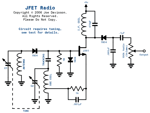
JFET Radio It's important to do the calculations and coil winding as accurately as possible. If done right, you should have a nice little reciever to experiment with. Note: nearby switching power supplies, such as those in computers, may prevent the circuit from working properly. Capacitors Turn C1 clockwise about 10% and measure the value, say 390pF. The broadcast band ratio is 1650/530 = 3.11. To find the lower end of the dial, do 390 / 3.112. This results in 40pF. The oscillator must track 455kHz higher than the broadcast band, and operates at 985 - 2105kHz. Measure C2 with C1 set at 390pF and 40pF. My values were 160pF and 16pF. The ratio is SQRT(160 / 16) = 3.16. But the oscillator band ratio is 2105 / 985 = 2.14. A tracking capacitor must be added to C2 so that the ratio matches 2.14. It is found with (160 + 16) / 2.142 - 16 = 22pF. In this circuit, the tracking capacitor also serves to couple the oscillator to the JFET gate. Coils |
Copyright © 2009 Joe Davisson. All Rights Reserved.