- Welcome to DIYstompboxes.com.

DIYstompboxes.com
News:
SMF for DIYStompboxes.com!
Recent posts
#1
Building your own stompbox / Re: Why the treble loss?
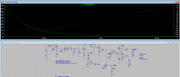
Last post by Rob Strand - Yesterday at 10:08:28 PMQuote from: fryingpan on Yesterday at 11:35:14 AMTo read output impedance, you need to turn off any voltage sources (LTSpice does this for you when it's DC, but you need to turn Vs off too) and actually feed a signal *after* the last stage to measure the output impedance, and measure the current.I often inject a 1mA AC *current source* into the output then read the voltage off directly in kohm.
Not to detract from antonis's result. When you have feedback biasing the output impedance is usually much lower than the collector resistor.
Also the output impedance depends what what is at the input: open, grounded, or a input series resistor (often used to set the gain) will change the output impedance. A shorted input and no series resistor will make the output impedance equal the collector resistor (well that in parallel with the feedback resistor, but that's usually high). A series input cap will make the output impedance change with frequency.
Here's an example: (image server was playing up)
[repost]
#2
Building your own stompbox / Re: Why the treble loss?
Last post by m4268588 - Yesterday at 10:04:06 PMQuote from: stonerbox on October 14, 2024, 04:00:47 PMI get treble loss after the recovery stage, why is that?
2nd order HPF
#3
Building your own stompbox / Re: Why the treble loss?
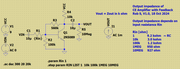
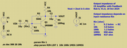
Last post by m4268588 - Yesterday at 09:25:11 PMV(OUT)/I(C29)
It matches with @antonis
https://en.wikipedia.org/wiki/Kirchhoff%27s_circuit_laws#Kirchhoff%27s_current_law
It matches with @antonis
https://en.wikipedia.org/wiki/Kirchhoff%27s_circuit_laws#Kirchhoff%27s_current_law
#4
Building your own stompbox / Re: Doulgas Self - Discrete Un...
Last post by Rob Strand - Yesterday at 06:24:44 PMFWIW,
Like all class A amp the output swing depends on the ratio of the bias resistor (in this case the source resistor RS) and the load resistance. When RL=RS we might expect the negative swing to limit to -7.5V.
The load resistance also affects THD. (As seen on most ckts in Self's book.)
The THD can be improved by making the drain more than 1k, say upto 3k9. The JFET operating current would decrease and noise would need to be evaluate; probably not changing much. Alternative the JFET current can be left as is and the source resistance reduced. RD=RS = 2k2 to 3k3 is a reasonable compromise.
The THD is less than 0.001% at 1V swing and RL = 10*RS, and increases as the input level increases.
Not bad for two transistors.
If using this as an output buffer things like stability with capacitive loads would need to be addressed. As least a resistor in series with the output lead.
For the base design I got about 3nV/rtHz input noise but that from spice, which doesn't model the JFET noise that well. Nonetheless, a 1k gate resistor will introduce 4nV/rtHz input noise. However a guitar pickup is going to introduce a lot more than that. The advantage of a JFET input over a BJT is the noise current is lower and that means the noise doesn't go up as much with high impedance sources.
A +/-15V supply pushes a lot of common JFETs. +/-12V would help.
#5
Building your own stompbox / Re: Doulgas Self - Discrete Un...
Last post by Rob Strand - Yesterday at 04:38:34 PMQuote from: fryingpan on Yesterday at 06:55:28 AMWhat are those values? Is it a 1k drain resistor and a 3.3k source resistor?The schematic has a few issues. What's weird is the mixed use of decimal points and EU notation: 3k9 and 3.9k!!!
The value of R87 is 3k9.

There's some scope to change the value although when you start getting to down to 600uA through R87 the JFET will operate at a small current.
QuoteI'd say that if the power supply is dual +/-15V, source should ideally sit at a negative value, like -13.5V.Yes dual supply and a source voltage something around +1.5V. Gate at zero, output a small positive voltage, at just under the JFET's |VP|.
#6
Building your own stompbox / Re: Digital controls for analo...
Last post by R.G. - Yesterday at 02:04:54 PMQuote from: amptramp on Yesterday at 01:32:08 PMI have seen motorized volume controls at a surplus store several decades ago and these were used as part of a remote control system. They used a 115 VAC bidirectional motor as the control element.Yeah, I have run into some of those. I always wondered about powering a 115Vac motor for a volume control.
The steppers were at hand (the stepper from a 5.25" floppy drive was perfect. Oh, wait! What's a floppy drive???
The stepper motor cogging added a nice feel to the pots in most cases.
#7
Building your own stompbox / Re: Why the treble loss?
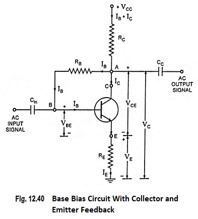
Last post by antonis - Yesterday at 01:55:56 PMNo need for precise measurements..
CE amp output impedance is roughly its Collector resistor value..
(actually, a bit less due to slight domination by parallel Collector internal resistance..)
CE amp output impedance is roughly its Collector resistor value..
(actually, a bit less due to slight domination by parallel Collector internal resistance..)
#8
Building your own stompbox / Re: Doulgas Self - Discrete Un...
Last post by antonis - Yesterday at 01:47:10 PMQuote from: fryingpan on Yesterday at 11:26:30 AMof course I had a brainfart.
Brainfarting is the distinctive feature of active brains..
#9
Building your own stompbox / Re: Digital controls for analo...
Last post by amptramp - Yesterday at 01:32:08 PMYou can implement some functions by multiplying DACs. Use a digital signal as the proportion control and the signal as the reference voltage and you have a simple digital attenuator.
I have seen motorized volume controls at a surplus store several decades ago and these were used as part of a remote control system. They used a 115 VAC bidirectional motor as the control element.
I have seen motorized volume controls at a surplus store several decades ago and these were used as part of a remote control system. They used a 115 VAC bidirectional motor as the control element.
#10
Building your own stompbox / Re: Why the treble loss?
Last post by fryingpan - Yesterday at 01:11:24 PMQuote from: stonerbox on Yesterday at 12:39:19 PMGET OUTTA HERE!
I was extremely suspicious to the results but wanted the jury's opinion before I went any further.


Like so.