 Yep, it's ground.
Where can I ask questions about this stuff?
Before you post on the forum, read this document and the fantastic GEO Guitar Effects FAQ. There are a few good places to ask questions about simple electronics and questions about building your own effects. My forum on this site is a good place to start. Ampage is a great online place that specializes in DIY stuff. A couple of good newsgroups are sci.electronics.basics and alt.guitar.effects. Please check out the beginner's page.
What is that upside-down triangle - is that ground?
Yep, it's ground.
Where do the connections that show a ground symbol go to?
Generally speaking, take all the ground points, connect them together, then connect them to the ground lug of the input or output jack. Take the power supply (i.e. battery) and connect it to the ground lug as well. If you want the input jack to switch your battery on and off, then connect the lug to ground as before, but connect the battery terminal to the middle connector of a stereo jack. When a mono jack is inserted, the ground circuit will be complete and the switch will be on. Note that some circuits connect the + or positive terminal of the battery to ground, although it is more common to connect the negative terminal to ground. The sleeves of the input and output jacks usually go to ground as they are usually connected to the metal casing and the ground lug - unless they are isolated jacks.
How do I wire pots?
Apparently there's a standard for the terminals. When looking at the bottom of the pot (side opposite the shaft sticking out) with the terminals facing left, from top to bottom they are labeled 3,2 and 1. The terminals correspond to the schematic terminal wires.

When viewed from the front, a pot turned fully clockwise connects terminal 2 to terminal 3. Fully counterclockwise connects terminal 2 to terminal 1.
Anyway, I know I have connected pots like this but they were still backwards. If that happens, simply swap the wires connected to terminals 3 and 1.
When do I use audio or linear taper pots?
You can use either one at any time. The taper may not be as optimum on some applications. The basic rule of thumb is use audio for volume and sometimes drive, use linear for everything else. That being said, you can use linear for everything. Linear pots will always "work". You can also turn a linear pot into a psuedo audio pot - read the next question.
What is the difference between linear and log or audio taper and how do pots work?
Check out The Secret Life of Pots at GEO.
I'm looking at a pot with the stem pointing at me. On the left side there is this little metal bit that sticks up. Why is that there?
From Joe Gagan:
Some electronics manufacturers
cast or drill a little hole in their enclosure to receive that
tab on the pot as an additional anti spin technology.
you can either add that hole yourself, or break off the little
tab with some pliers like most of us around here do.
I'm testing out a pedal I made and I want to test it out with a function generator. What kind of signal should I use?
From Zachary Vex
Put the output of the function generator on a scope, set it for around 400 Hz, sine wave output, 100 mV peak-to-peak, and use a 47k resistor in series between it and the input to your pedal. you can increase the output to as much as 1 V peak-to-peak safely, i think, and you should monitor the output of the generator on a meter or with one trace on the scope while you monitor the output of the circuit with the other trace, if it's a dual-trace unit.
What's a cool drill bit to buy to drill these metal boxes?
Try a Varibit (possibly called a UniBit as well?). These are stepped drill bits that cover pretty much all the holes you need to drill. I bought the smallest size bit and it worked for everything up to footswitches. About $20 in my local store.
What kind of capacitors should I use?
In a nutshell, you should use
electrolytic or tantalum capacitors when the capacitor is polarized.

For any others, the basic consensus is to use film caps if they fit, otherwise use a mixture of film and ceramic capacitors. For most of our circuits, use caps with a minimum 16 volt rating. R.G. posted a great explanation about the subjective world of capacitors. For distortion circuits, others have noted that cheap ceramics sound good too, so use your ears! In general, 1uF and up will be electrolytic, any smaller values up to .001uF can be film types and picofarad values like 10pf-470pf are usually ceramic types. This is usually due to size, cost and availability.
I can't find xx uF capacitor!
You can put two or more capacitors in parallel and their values will add up. This way you can substitute common cap values for hard to find ones.
I saw this weird capacitor symbol on a schematic, it had plus signs on both sides! What is this?
It's a non-polarized capacitor.
From Jack Orman:
You can simulate a non-polarized by using 2 electrolytic caps. Connect them together negative to negative and use the positive leads as the component leads; which is probably why someone notated it as +-||--||-+
Each of the capacitors should be double the value that you need for the circuit because of the series capacitance formula:
Ctotal= 1 / (1/C1)+(1/C2)
I don't really understand the units of measurements.... uF, pF etc....
Read R.G.'s great Units Tutorial....
Can I put a non polarized capacitor in place of an electrolytic (one that has plus and minus signs)?
Yes you can. It's more troublesome to do the other way - to put an electrolytic in place of a normal capacitor since you have to orient the capacitor the correct way or bad things could happen. Don't do this on high power circuits though. For most 9V stompboxes, this should be fine. How do you know which way to orient the polarized cap? The side with the larger voltage faces the positive side of the cap.
In general - how do I orient an electrolytic capacitor?
The positive side of the polarized capacitor goes to the side with the higher voltage.
What is PCB and RTS???
Printed Circuit Board and Ready to Solder when related to stompbox electronic projects.
I see this symbol and I know it's a battery, but which end is positive?

The end with the longer line line (in this case vertically) is the positive terminal, so...
 the left side is positive and the right side is negative.
I see V+ mentioned in some schematics, for a 9V battery powered device, does this mean the PLUS end of the battery?
Yes. You make sure that all V+ connections are connected together and that the PLUS or POSITIVE side of the battery is connected to them. V+ basically means the most positive voltage of your pedal; usually 9 volts. V+ is sometimes also called Vcc (+). Vcc(-) in most circuits we use would be ground (or the most negative voltage).
What is V.R., V.B, VREF, 1/2V+ etc....?
Well, V.R. is voltage reference and 1/2V+ is 1/2 of your most positive voltage (usually 9 volts). Usually they are one and the same and you can typically see V.R. connected to a resistor that connects to the input of an op amp as in the Shaka Braddah 3, The Rat and many others. Basically if you see 4.5V or V.R. or 1/2V+ ( all the same), you find all the places on the schematic that reference the label and connect them together. So all of the places that reference V.R. would connect together; one of the connections actually creates V.R. or 1/2V+. The connection that usually creates V.R. or 1/2V+ aka 4.5V (for a 9V battery) usually is a voltage divider. Typically two identical resistors, one to V+ (such as 9V), the other to ground. The place where they connect is V.R. or 1/2V+.
 An example of 1/2V+ also known as V.R., V.B., VREF,
1/2V+ etc...
An example of 1/2V+ also known as V.R., V.B., VREF,
1/2V+ etc...
I'm looking at a PCB and I see points A,B,C,Grnd,V+ etc... Where do they connect to???
They are usually places where you put a wire into the board and it connects to a potentiometer or ground wire of the input jack or the plus side of a battery. Look at the schematic for the PCB and these points should be labeled.
I would like to try running my pedals at 18 volts with 2 batteries. How do I get 18 volts out of 2 batteries?
Take 2 battery clips, connect the black (negative) of one to the red (positive) of the other clip. Now use the two remaining clips as usual, when you measure the voltage with a multimeter with fresh batteries, you will measure around 18 volts.
I want 18 volts but I want to use one battery.... is this possible?
Yes. Check out this simple Voltage Doubler Circuit. Check out GEO's, circuit sweepings! In general, if you can, use 2 batteries - it's easier.
How can I get a negative voltage out of a single battery for a bipolar power supply?
Check out the ICL7660, 7662, LT1026, voltage converters. They can double, produce negative voltages etc... from a single battery.
How do I make the input jack switch the power on and off?
Get a stereo 1/4" jack for the input of your pedal. Connect the tip connector to the input of the effect. Connect the sleeve to the ground of your effect. Connect the 3rd connector (the ring) to the negative of the battery (or the positive if your pedal uses a reversed power supply such as the Tycobrahe Octavia or some Fuzz Faces). When the cord is inserted into the jack, the ring connects to ground completing the circuit.


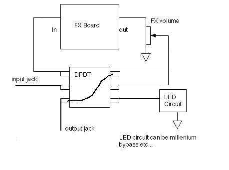
What is true bypass and what is a DPDT switch?
Read this excellent article by R.G. Keen on bypass methods.
How do I wire a DPDT switch?
Check out this picture.
Where do I purchase a DPDT switch?
Order from Small Bear Electronics (Carling 316) for about $9 each.
What's the deal with the cheaper switches I see available... can I use them?
Yes. You can use any type of DPDT stomp switch, the issue is reliability. As of 7/1/01, there is no better switch than the tried and true Carling switches. The other "Arrow" copy DPDT switches are fine for home use where you can swap them out anytime if they fail (and most cheaper switches seem to fail). For gig use, I recommend Carlings. I have heard the Fulltone 3PDT switches are good, but expensive.
I have an Ibanez Tube Screamer and the switch broke, what can I replace it with?
From CJ Landry:
The part is made by E-Switch with
the part number TL1100 and the Mouser P/N is 612-TL1100. I have
been using this part for a long time when replacing the TS-9 style
switch. You might want to add a second source. The second source
is also a Mouser part made by Mountain Switch. It's Mouser P/N
is 101-0621. The difference between these switches is the square
top (on the plunger). The size seems to differ between the E-Switch
part and this Mountain Switch part. I have not looked at detailed
specs for each switch, but would try the switch which has a longer
operating life. This is the number of switch actuations it can
handle before it fails. They both work fine and I have no personal
preference.
I get oscillation/squealing from my distortion when it's bypassed. How do I stop this?
Your pedal has such high gain, that the input needs to be grounded when the effect is bypassed. Jack Orman's alternate wiring method does this. If you need an LED+input grounding, use R.G. Keen's Millenium 2 bypass with extensions.
I am picking up radio stations, how can I stop this?
From Eric Hensel:
A 47pf cap to,ground, after the
input cap will probably do it --you can adjust this up or down
--higher values will start to cut treble. use the lowest value
that works.
From Zachary Vex:
mount the pc board as close as you can physically to the metal box. this will serve as a ground plane to reduce the heterodyning that can pick up rf. don't let the input and output wires cross... make sure the layout doesn't allow input and output connections to get too close to each other. if you can, solder in ground connections around (near) the sensitive input circuitry. if rf is being picked up by rectification, these fixes won't help, but if it is being picked up due to beat frequencies generated by heterodyning (internal rf oscillation in the circuit beating against rf from radio stations) you can get rid of it through the use of careful layout and grounding to reduce oscillation.
you might try using miniature shielded cable inside of the enclosure for the input to the board too.
I get a pop when switching my effect in and out. How do I stop this?
The typical method is to put a "pulldown resistor" from signal to ground at the front and end of your circuit. This is implemented as a 1 meg resistor from signal to ground. Just put one at the beginning of your circuit board (before the input cap) and another at the end (after the output cap). Look at the many GEO layouts if you need to see a layout using these resistors. If you are not using high quality switches, it could also be the switch.
How do I make an LED that shows if my effect is on? Can I do it using a DPDT?
Yes! Check out the GEO Millenium Bypass. I have used the Millenium B ypass with both MPF102 and J201 FETs. The J201 worked well with the white blinking LEDs I got from Radio Shack. The MPF102 worked ok with the Red LEDs I used. Look at the very clear diagram that Jack Orman wrote for hooking up the circuits. If you make the Millenium Bypass, the wire labeled To Switch connects to the DPDT switch. The +9Vdc connects to the plus terminal of the battery or any +9V connection on the board. The Ground wire goes to any ground on the board or the ground on the jack. The rest of the DPDT is hooked up like the diagram that Jack Orman wrote up. You don't need a 3PDT anymore!
What is a breadboard/proto board? Can I test circuits on this?
Yes! A breadboard/proto board is a board with holes that are connected in preset ways. For instance rows of holes will be connected (i.e. wired) together and all you do is stick components into the holes. So to connect a resistor to a capacitor, all you do is stick the resistor lead into a hole, then the capacitor lead into another hole that is "wired" to the first.
It's relatively easy to test circuits on a proto board because you can easily substitute different components. The drawback is that the proto board layout can end up not even remotely resembling the layout of the perf board or PCB.
What is Si, Ge??? I see this all the time?
Si = Silicon, Ge = Germanium.
Give me a quick rundown on basic diode types....
From Rob Strand:
You need to find at least one of each types too have a look at. Most diodes of the same type look similar in size. The size grows and lead thickness grows with increasing current handling. Most diodes have a band at one end which is the cathode and many have a part number stamped on them. Diodes can look similar but may be completely different!!
Here a _quick_ rundown on the key points:
Germanium: 0.3V, low currents, fast, usually clear+striped bands
Small signal silicon: 0.6V, low currents, fast, small glass, often copper coloured. Few variations: blue/green/yellow stripes and no part number, black bands with part number, multiple coloured bands and no part number.
Power silicon: 0.6V, high currents,
slow, usually black plastic with silver
or white band and usually a part number.
Power silicon-fast: 0.6V, high currents, fast, look same as Power silicon.
Small Signal Schottky: 0.35V, look like small signal silicon and zeners
LED: 1.8V, unmistakeable, different colours available.
Zener: 0.6V one direction and zener voltage in other direction,
look like small signal diodes but are often coloured with
a part number stamped
Small diodes without part numbers are very hard to identify exactly but are usually small signal silicons or maybe zeners (if it has a number like 5B or 0A (for 5V, 10V) stamped on it).
What is germanium? Where do I find germanium transistors and diodes?
Germanium is a metallic semiconductor and early transistors and diodes were made from it. You can read about the history of the transistor here. Some early circuits like the Fuzz Face and Tone Benders used germanium transistors. You can find germanium transistors from NTE as well as other electronic places. GEO and Small Bear Electronics offer matched transistors for building these circuits. The typically used germanium diode, the 1N34A is available from Radio Shack and other places.
Can I just stick a germanium transistor instead of silicon in a circuit?
In general, no. You need to rebias the circuit for the germanium transistor.
What's up with this "matching" transistors for Fuzz face type circuits? Do I have to do this?
No, you don't have to match them, but the circuit may not sound as good. It has been noted that matching transistors in the Fuzz Face could give you that elusive sound that the highly sought after Fuzz Faces had. GEO has a great article that explains this and most boutique pedals carefully match their transistors by hand. Small Bear Electronics has a great article as well! You can do this too. Just buy a ton of transistors and measure each one until you hit the "magical" points on a couple of transistors. Of course this could cost $$$. For a great alternative, utilize the services of the pros! See below!
Where can I find germanium transistors for Fuzz Face circuits?
Darn it! I just bought a TON of NPN Germanium transistors... I thought they were PNP. Can I use them?
Hah! This happened to me. Well, it's pretty darn easy to convert PNP circuits to NPN. Reverse the polarity of the Electrolytic capacitors, diodes and the power supply. It worked fine for my Fuzz face and Tone Bender.... Very nice!
Why does my pedal have a horrid crackling or "gating" sound when I play? I have to hit the strings really hard to get it to make sound and it's horrible.....
You have a classic case of a mis-biased transistor(s). Check out the Guitar Effects Debugging page, especially the section on bias problems.
How can I find out more about transistor biasing?
From R.G. Keen:
By far the most comprehensive
and comprehensible book on transistor bias and gain that I've
run into is "Practical Transistor Circuit Design and Analysis"
by Gerald Williams; 1973 McGraw Hill, TK7871.9.W53, ISBN 0-07-070398-1.
I see 2N5088 all the time but it's NPN, what's a PNP substitute for the 2N5088?
From R.G. Keen:
Use a 2N4250. 4250 is not exactly a complement of the 5088, but it's pretty good for any silicon PNP uses.
What's a generic replacement for NPN and PNP transistors?
From R.G.
Keen:
When in doubt, use a 2N5088 for NPN's and a 2N4250 for PNP's.
I've got one of those SKB powered pedalboards. Is it possible to lop the tip off one of the power cords and rewire it with reverse polarity to power a PNP pedal?
From Zachary Vex:
Only if it's the only pedal you
are powering with the power supply. if you are also using that
same supply normally with other effects, you'll be shorting +
to - at the ground connection when you attach one pedal to another...
think about it. the plus side is ground on the PNP box, and minus
is ground on the others, then you connect the grounds together...
fizzle!
the only way to do it is to connect a second supply that allows
you to make the negative connection on your PNP pedal BELOW ground
level. so you can lop off a connector and reverse it to power
a positive ground (PNP fuzz face) pedal, but it has to be connected
to a different power supply.
How can I measure how much current my pedal is drawing?
From F Peña:
You have to interrupt the circuit
to measure current.
Do this:
Set you DMM on DC/mA.
Plug only the - side of the battery to the battery snap.
On the + contact of the battery touch the red probe and on the
free
contact of the battery snap touch the black one.
You should get the reading on the meter this way.
What is the best way to add a 9V wall wart to my fuzz clone? What can I add in terms of filtering to insure, or at least cut down noise for low noise operation?
From Rob Strand:
The simplest suggestion is to put a 100 ohm resistor in series with the power rail (ie. -rail for PNP, +rail for NPN, not that it really matters) then a 100uF electro across supply, on the effect side.
Phillip Marshall contributed even more ideas!
What's a replacement for the 2N5088?
From R.G. Keen:
2N5089 will work in most instances. Also useful are 2N5210, 2N4401, BC549.
What FETs can I substitute in the Mini-Booster and Shaka etc...? I can't find the J201....
From Jack Orman:
This is a recurring question even
though the information was in the Mini-Booster article at AMZ
From the article: "The NTE458 usually has more gain than
the J201, and the 2N3686 can provide gain of 500. The 2N5457,
MPF102, and 2N3819 will produce less gain. Other substitute transistors
include 2N5484, 2SK43, 2SK68, 2SK117, 2SK118, 2SK121, 2SK163 and
BF245."
What is the pinout of the J201?
It's the same as the MPF102 (see pinout diagram at the bottom of this page). Flat side up, legs pointing down, DSG from left to right.
The J201 is available from Radioshack.com and Future Electronics (global).
Is there a general spec that tells me if a FET has more gain or not?
From Jack Orman
"FETs with a low Vpinchoff usually have high gain. The Yfs (or Gfs) spec is a general indicator of gain as well... Yfs of 1000 is low gain, 3000 is moderate and 12000 is smokin'" (Thanks to Jack Orman for this tidbit!)
Do JFET circuits need a DC blocking capacitor? I see some that don't have them.
From R.G.:
Most JFET amps, like most triode
and pentode amps don't need an input blocking cap under most conditions.
This is because the correct bias voltage for most of these circuits
is with the gate (or grid) at zero volts and the source (or cathode)
a few volts higher. JFETs, triodes, and tubes are -depletion-
devices which means that if you do nothing to them, they conduct
like mad. Bias for all of these devices involves holding the gate/grid
-lower- than the source/cathode to turn them partially off. This
is most often done by holding the gate/grid at zero volts and
placing a resistor between the source/cathode and ground.
At turn on, the gate/grid and source/cathode are both at zero
volts, so the current increases through the drain/plate. This
same current has to flow through the source/cathode resistor,
so it pulls the source/cathode up above ground, reverse biasing
the gate/grid a little. Eventually the source/cathode rises enough
that the voltage between it and the gate/grid is just right to
keep that amount of current flowing and so it stabilizes at that
current. It's so-called self biased.
This is different from bipolar transistors and enhancement mode
MOSFETs. These devices are normally off, and you have to do something
to the control electrode to make them turn on a bit.
In any case, the correct voltage for many JFET and tube circuits
is zero volts DC on the gate/grid, and that just happens to be
the only voltage that doesn't need a coupling cap.
Where can I get a simple explanation about biasing a FET as an amplifier?
Read about a FET amplifier here at Graham Knott's page.(Thanks Mike B.)
What about biasing a silicon transistor?
Check out this page .
I need to find that JRC4558 chip that's in the TS-808, I heard you can get them from old radios and other voodoo sources!
Yes, you probably can. Or, you can buy the current chip that sounds the same as the original - so close you can't tell the difference... from MOUSER. The part number is:513-NJM4558D. There's more about the TS and chips here.
What do all the letters after the numbers mean at the end of an IC?
From Rob Strand:
General letter usage (not just
TLO7x, and all options may not be available):
The A and B refers to offset voltage categories. Non-A/B versions
have the highest, then A, then B.
The C, I, M referes to the temperature range, widening/increasing
in that order.
The P, N, H, J refers to the package type/material. Usually D
means a surface-mount package.
Sometimes the different package material implies different operating
temperature ranges.
Basically you are safe with any of these except D. For Audio projects
usually the cheapest is OK. Using low offsets, wider temp range
and different packages _usually_ means you pay more, and if you
don't need the options you're wasting your money.
Where can I find CA3094E chips?
While supplies last at NEWARK electronics, part# 06F2063:
Discontinued/Non Stocked Parts
Newark Part Number: 06F2063
Mfg. Part Number: CA3094E
Category: Semiconductors/ICs & Accessories/Discontinued/Non
Stocked Parts (Search This Category...)
Description: INACTIVE
Also at newtube.com . Thanks to Paul Perry and Doug.
I live in another country, what's a good place to order from?
Try Future Electronics - a global company with lots of transistors!
What are these boxes? What's a delay, phaser, phasor, etc...?
Check out Harmony Central's effect description page or R.G. Keen's effect descriptions page.
What did these things look like?
Check out this book The Stompbox by Art Thompson. Here's another place (Stompnet)
You've got so many schematic links here. I don't know what these stompboxes sound like? Which one's should I try?
Yes, there are a lot of schematics. Someone obviously thought the stompbox sounded good enough to document... Here is a link to Harmony Central's Effects database. Users write in and voice their opinions. Another way is to look at what stompboxes custom manufacturers are bringing back. Stompboxes like the Colorsound line, the Big Muff etc... If they are bringing it back then it can't be so bad. Try the most popular ones and then try the more esoteric ones. Check out www.tonefrenzy.com for great samples that you can listen to. I have online samples as well.
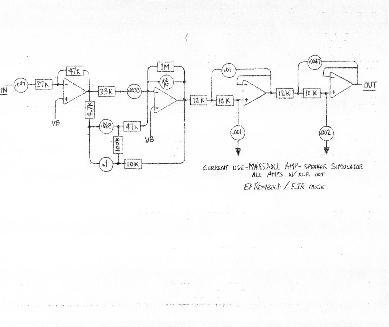
I wish I could make a cabinet simulator; that way I could record direct and play through my boom box etc...
You can. Check out the Marshall type cabinet simulator. This does not replace a miked amp, but is usable and sounds good when going direct.
Where do I find the boxes to put this stuff in?
Commonly called "enclosures" in your favorite catalog, they are made by Bud, Hammond, LMB etc... Aluminum boxes are easy to work with compared to steel. If you want a solution that's cheap but a little harder to work with, check out electrical outlet junction boxes. Thanks to Jack Orman for the tip.
I have been using the 1590BB Hammond box that R.G. recommends. It is so great to build into a box that is sturdy, has enough room and looks good. Small Bear Electronics is now offering the 1590BB for $9.40, a very good price!. For a smaller box, check out these aluminum enclosures.
What does 4K7 and 1K2 mean for resistors?
"That is just the european notation. They replace the decimal point with the multiplier letter. This prevents the possible loss of the decimal point in transcribing data. For instance, 4.7K = 4K7, 1.2K = 1K2, 1M = 1M and so on.
You'll also find the Euro use of "nanofarads", meaning 1/1000 microfarad or 1000 picofarads. For example, 0.001uF = 1nF = 1000pF. 0.022uF = 22nF.
It's handy, and less error prone."
(Thanks to R.G. Keen for
this reply in the DIY forum!)
I don't have xxK resistor!
You can put two or more resistors in series and their values will add up.
I recently read somewhere that using carbon composition resistors in an effect circuit would help to create "brown sound". Are carbon comp. resistors really better to use for audio circuits?
Here's a nice article written by R.G. on carbon comp. resistors.
I see that a lot of pedals you use have FETs, what other types of FETs can I use since I can't find many of them?
Here are some FETs that you can try:
2N5457, 2N5484, NTE458 , ECG458, or J201. The J201 can be found at www.techamerica.com and Future (1800-655-0006). The NTE and ECG FETs should be at most major electronic stores. The 2N series can be found at www.mouser.com as well as all the other places I list.
How do I measure transistor gain?
The easiest way is to get a multimeter that can measure transistor gain (hFE). The cheapest one I have found is from Hosfelt: 9202 - Multimeter, just $12.95.
Are there other tests I can do with just a multimeter?
Yep, check out: Basic Testing of Semiconductor Devices.
I'm looking for a multimeter, is there a good, reasonably priced one?
I checked all over the place and the best one I found for a mid-priced one is the Radio Shack True RMS Digital Multimeter. At $99 it's great ($15 off if you join Sprint :-))
It has True RMS, Capacitance, hFE (transistor gain), auto pinout identification for transistors, slots for testing resistors and capacitors and diodes (don't have to use leads), temperature and best of all, it's auto-ranging!
The catalog number is: 22-174B.
Try and find another multimeter with more features at this price!
--- Update --- here's a good one from Sears.
The SEARS, multimeter part number 03482139000, does almost everything we could want except transistor gain hFE.
How do I put jacks for 9V adaptors on my pedals?
JD did all the work here:
Effects Power Switching and Adding a Power Jack.
Where do you buy your transistor sockets from?
Mouser part: 151-TO-1832OG. 151-TO-4320G and 151-TO-18320G. Most 3 pin sockets will work fine.
How can I protect my circuit from a backwards battery?
Check out this article from geofex.com on circuit protection and other tricks.
I can't find a xxxxx transistor! Where do I find a replacement/substitute???
Try this: go to www.nteinc.com,click on Semiconductor (for searching) and type in the transistor number. If there is a replacement made by NTE, it will be shown and you can look at the data sheet if it's online. Since NTE and ECG share the same numbers, you should be able to find either NTE or ECG parts at your local electronics store. Usually these replacements will work fine. Only in very special circumstances will the replacement parts fail to work.
From Jay Doyle:
The best advice I could give anybody
getting started in DIY effects, is to go to the Free Trade Zone
and sign up:
http://www.freetradezone.com/index.html
You can search by part number, manufacturer and keyword. They've
had pretty much everything that I've ever searched for except
some obscure transistors.
The search results give you every model made by each manufacturer
with datasheets, applicable appnotes and has a parametric search.
After that you can search their database to find the lowest price
at something like 40 different companies.
How do I find out the pinout of a transistor or op amp?
For the most part, go to www.nteinc.com,click on Semiconductor (for searching) and type in the transistor number. If there is a replacement made by NTE, it will be shown and you can look at the data sheet if it's online. On the bottom of the page will be a picture of the pinout. IN MOST CASES, the pinout will be exactly the same as the original part. If it's different, the NTE web site will note that the pinout is different.
Since NTE and ECG share the same numbers, you should be able to find either NTE or ECG parts at your local electronics store.
Also check out these datasheets:
How can I change the kind of distortion I have - or make it more fuzzy?
Read this detailed message from Mark Hammer.
When should I use silicon or germanium diodes?
Read this detailed message on diodes from Mark Hammer.
Anything more on diodes?
Doug Hammond pointed out this link: The Unusual Diode FAQ.
How do I isolate my jacks from the enclosure?
From R.G.
Two choices:
(a) get insulated bushing jacks like the Switchcraft N1xx types
or the ReAn nylon body ones (excellent choice, that). Mouser has
both.
(b) buy the white nylon bushings that Mouser offers. These fit
a 1/2" hole and have a 3/8" hole for a standard jack.
They're used a lot in isolating input jacks for tube amp hum reduction.
From JD
If you want to go with the nylon washers, here are the Mouser part numbers for the washers that work with Switchcraft jacks
561-SW375 - Nylon Shoulder Washer
561-D37562 - Nylon Flat Washer
How do I debug and fix my effects?
Check out GEO's FX Debugging page and mine.
I am getting a whine - like feedback but high pitched when I turn the drive all the way up...how can I fix this?
You probably are running the leads of the input and output too close or they are too long. Keep the leads as short as possible when laying out your box. You may also want to consider using shielded wire. To do this, shield the wire on one side only and then connect the single conductor like usual. For high gain boxes, I recommend shielding the input and output wires from the jack to the switch and from the switch to the board.
What kind of shielded wire should I use?
If you can get it, single conductor with shield - RG-174 Belden wire. Very good and it's flexible too.
What kind of wire should I use in my pedals?
In general any type of hookup wire will work - from size 22 gauge and smaller. (The larger the number, the smaller the wire - so 26 gauge is skinnier than 22). I like the "pre-bonded hookup wire" from Small Bear Electronics. It's a cross between stranded and solid core - very nice. In general solid core will stay where you want, but will not like being moved and can break easily. Stranded is much tougher but resists bends and will generally not look as "neat" in an enclosure. If the circuit is being mounted in an enclosure and will not be removed - solid core is ok. If the it's going to be moved at all, I recommend stranded wire or the hookup wire mentioned above from Small Bear.
Where can I get a printed circuit board (PCB) layouts or ready-to-solder board (RTS) for effects?
Check out Lazyfinger.com or GEO.
How do I cut fiberglass PCB boards?
From Paul Perry:
I had to do this for a coulple of dozen boards.. Found the best way was to get a 'tile scriber' which is just a knife sized handle with a tungsten carbide point stuck on. You just clamp the board with a metal edge on it & scrape away heavily a few times, then snap on the scoreline. OK it's trivial & obvious maybe, but I tried to cut them in a bandsaw, DONT even think about it, also fibreglass powder is BAD for your lungs.
I would like to try and write out a schematic of my effect. How do I do this?
Read GEO's article on this.
What capacitors/resistors do you buy? Where do you purchase them from?
Check out my purchasing parts page.
What's an easy-to-use PCB program?
I have heard Easytrax is everything we need for making PCBs.
What can I use to view/create PDF files?
You
can write PDF files with Ghostscript for free.
Where can I check out patents? I would like to see what others have done before....
Try these:
http://gb.espacenet.com/
http://fi.espacenet.com/
http://www.uspto.gov/patft/
What is the formula for calculating the knee of a RC circuit?
From R.G. Keen:
A resistor and capacitor are halfway to whatever they will do - highpass or lowpass - when the capacitive reactance equals the resistor. That is, when Xc = 1/(2*pi*Frequency)= R, the filter is at its knee. So with a little elementary algebra, Freq. = 1/(2*pi*R*C).
The units are ohms, hertz and farads.
For the TS series feedback loop
(for example), this comes out to
(1/F)= 2 * pi * (.000000047Farad) * (4700 ohms)
= .001387 Sec
F = 720.8Hz.
You can play games with the decimal points. If you use C in uF and R in megohms, you get
F = 1/(2*pi*.047uf*.004700M) = 720.8Hz
But I prefer not to mess with remembering special cases of uF/Mohm, etc. Just do it in farads and ohms and keep the decimal point straight.
How can I make my own knobs?
From R.G. Keen:
Easiest is to cast them from casting resin or sculpt them from Bondo auto body putty or Sculpy plastic clay. Find some plastic knobs you don't like, and break the plastic away from the brass insert inside the knob to get the insert with its threaded setscrew.
For the bondo version, make a filler plug of parafin wax to keep the hole to the threaded hole free and insert it into the setscrew hole. Wouldn't hurt to stuff the shaft hole full, either.
Then mix up the body putty, and start building up the knob body. As the stuff cures, it goes through a "cheesy" phase where it's really easy to cut and shape. Once it fully cures, it is hard and solid, can be sanded to a very smooth surface or sculpted by a Dremel with a burr on it. Then paint.
For the Sculpy (FIMA is another trade name) just sculpt the stuff on the insert like modelling clay, and bake it according to the directions when you get it right. Not as durable as Bondo, but easier to work.
If the design is fairly simple, make a wax model of the knob, pour plaster over it to make a mold, and then melt out the wax. Pour in catalyzed casting resin until the level just supports the insert, let it harden a bit to hold the insert in place, then do another pour to complete the knob. As with the bondo, use parafin to keep the setscrew hole and shaft hole free of the casting material and melt it out later.
Other people must have asked a ton of questions about all sorts of stuff before right???
How can I make a Triangle Knob Big Muff? Where's the schematic? Where's the schematic for a 70's Big Muff.
What's up with the swell circuit on the Foxx Tone Machine PCB?
I have an ole 3 knob memoryman delay, NOT STEREO. I play it and it passes signal when on and off but no effect. Do you guys think it is the rare mn3005 delay/chorus IC gone bad???
Here is a picture of various types of capacitors. Picture courtesy of Brad Fajardo
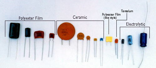
The most common types are Ceramic (they are cheap and generally used for small values), Polyester Film (common at Radio Shack) and Electrolytic. The other types can be used but are more expensive. Electrolytics are polarized; i.e. they have positive and negative terminals, just like a battery.
There are two very common packages of electrolytics that you will run into; Axial and Radial. As you can see below, the difference is where the leads exit the capacitor. I like Radials because they take up less space on the board.

This is what a typical electrolytic capacitor looks like. The side shown is the NEGATIVE side of the electrolytic. I have read in books that the the positive side is sometimes marked, but so far I have only seen the negative side marked in the capacitors I buy in the local stores.
 Radial capacitor with negative side showing.
Note the 16V on the electrolytic, this is the voltage rating of the capacitor. For our stompboxes, 16V or 35V or anywhere in between is fine,. When you shop around, try and get the cheapest capacitor in this range. Sometimes the 35V will be cheaper than the 16V, same money and buy the less expensive one.
Here are some common electrolytic symbols that you may encounter. In the following example, the negative lead would be facing down and the positive lead facing up.
Here's a link to a page that describes how to read capacitor values. Here's more about capacitors. Even more confusing stuff about caps!
As usual, R.G. posted a great explanation about the subjective world of capacitors:
DIODES
Diodes are polarized similar to electrolytic capacitors; there's a positive and negative end. The cathode is the negative end of the diode and the anode is the positive. The main thing for you to remember is that you need to orient the diode correctly with the schematic.

LED is a light-emitting diode. It has a cathode as well and it is usually marked with a flat side or dot or in some cases a groove in the LED. Read more about different LEDs.
You will have to work with transistors in some stompboxes. The middle line is usually the base (B). One of the lines will have an arrow, that's the Emitter (E), and the last line will be the collector (C). If the arrow points away, it's an NPN transistor. If it points in, it's a PNP.
 NPN
Transistor
NPN
Transistor PNP
Transistor
PNP
TransistorOnce you have identified the lines on the schematic, you need to identify the pinouts on the transistor and match them to the schematic. Refer to the diagram that comes with the transistor . Lots of transistors use standard package types. Some transistors have unusual pinouts so always check the diagram or obtain a datasheet on the transistor.
![]() this
picture shows the FLAT side up of the transistor. You will
often see this picture in pinout diagrams. Sometime they don't
tell you this is the flat side...
this
picture shows the FLAT side up of the transistor. You will
often see this picture in pinout diagrams. Sometime they don't
tell you this is the flat side...
For all the circuits that use FETs, I now recommend the J201 FETs from Small Bear Electronics. At ~45 cents each, they are reliable and great! The have the same pinout as the MPF102 in a TO92 case. Future Electronics also carries the J201 FETs and is a global company shipping all around the world.
If you cannot get the J201, I also recommend using NTE458 FETs instead of MPF102. The NTE458 is about $1.80 around here.
Here is an example of a FET in a schematic that you might see:
 FET
FETMany schematics will omit those markings. Refer to this picture if you get confused.
A common thing is for transistors to use a specific package type.
Here are some common pinouts for some standard package types. Note that there are variations in pinouts and variations of T092 etc... Check your datasheet, which describes the pinout of your component.

If the circuit uses an IC (usually an op amp), then you will see something like this in the schematic:
 IC in schematic
In this case, you need to look up the datasheet for the op amp. Note that you can use a TL071 and have a great low noise substitute for a 741 chip.
In this case, lets pretend it was a TL072 op amp. Here's the pinout:
 (almost all?)Dual Op Amps have this pinout.
Referring to the IC in schematic picture above, the wire going into the minus sign is the Inverted Input/pin 2. The wire going into the plus (+) sign is the Non-Inverted Input/pin 3. Vcc refers to the Vcc (+) input /pin 8. The ground goes to Vcc(-)/pin 4. The wire exiting the IC in schematic is the Output /pin 1. Since the TL072 is a dual op amp, there are two sets of Input and Outputs. Sometimes circuits will use both amps (inputs and outputs), sometimes it will use only one set. In both cases, Vcc(+) and Vcc(-) will have to be connected. Vcc(+) goes to positive power. Vcc(-) goes to ground. If the only one of the op amps are used, the other set of inputs and outputs can be left disconnected. In some schematics, the Vcc(+) (power) and Vcc(-) ground will not be shown. This does not mean you don't have to connect these pins, you have to; the schematic writer is assuming you already know this..
Let's look at a typical circuit using a popular chip, the LM741. This chip was used in the MXR Distortion+, Dod Overive and many others. Although widely used, it's a noisy chip. You can replace the chip with another lower noise op amp like the TL072. if you are building your own circuit. Note if you are modding an existing pedal, use the TL071 - a direct chip replacement.
example circuit using 741 chip
 <-
LM741 Chip pinout
<-
LM741 Chip pinout
See how the -(minus) sign is the Inverted Input? See the power V(+) on pin 7 and the ground which is pin 4 V(-). To use a TL072 or equivalent, you need to map the LM741 pinouts to the TL072.
TL072
LM741
To use a TL072 instead of an LM741:
The connections that connect to Output pin 6 of the 741 connect to pin 1 on the TL072
The connections that connect to V(+) pin 7 of the 741 connect pin 8 of the TL072
The rest of the connections are the same.
Always use IC sockets on your board. That way, you don't expose the IC to heat when soldering and you can always substitute a different IC later. For example you can try an RC4558 or TL082 etc...
Here's a link to some op-amp basics.